In an era of rotating drones, 360° cameras, and robotic arms, USB-C slip rings have emerged as unsung heroes, enabling seamless power and data flow across continuously rotating systems. These compact electromechanical devices solve a critical challenge: maintaining reliable electrical connections in applications where unrestricted rotation is essential. But as demand grows for higher power delivery and faster data speeds, engineers face a daunting balancing act.
USB-C slip rings are not mere passive connectors—they must juggle the robust demands of USB Power Delivery (PD) (up to 240W) and the precision required for high-speed data protocols like USB4 (40Gbps) or Thunderbolt 4. For engineers and product designers, this duality creates a labyrinth of trade-offs. How do you ensure stable 48V power transmission while preventing signal degradation in a spinning interface? Can a slip ring’s contacts withstand arcing under high current and preserve the integrity of multi-gigabit data streams?
This article dives into the technical tightrope walked by developers of USB-C slip rings. We’ll dissect why optimizing for power delivery often clashes with high-speed data transfer goals—from material limitations to thermal constraints—and how these compromises impact real-world applications. Whether you’re building a precision robotic arm, a surveillance camera requiring uninterrupted 4K video, or a consumer drone that charges mid-flight, understanding these design challenges is key to avoiding costly pitfalls.
What Are Slip Rings?
Definition & Functionality
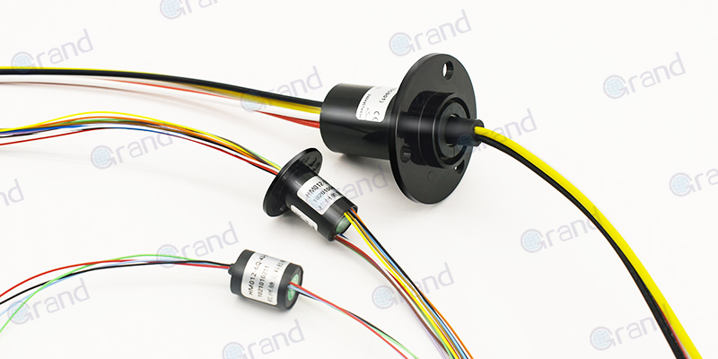
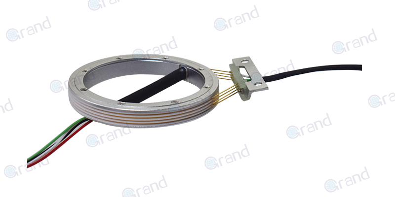
Slip rings, also known as rotary electrical interfaces, are electromechanical devices designed to transmit power and electrical signals between stationary and rotating components. Unlike traditional connectors that disconnect during rotation, slip rings maintain a continuous electrical connection through sliding contacts (typically made of precious metals like gold or silver) that brush against conductive rings. This enables 360° unrestricted rotation while preserving signal integrity and power delivery – a critical requirement in dynamic systems.
Key Applications
Robotics:
Enable robotic arms to rotate infinitely without cable twisting (e.g., industrial assembly lines, surgical robots).
Provide real-time feedback from rotary joints via embedded sensors.
Wind Turbines:
Transfer generated power from rotating blades to stationary grid connections.
Transmit pitch control signals for blade angle adjustments.
Medical Imaging:
Found in CT/MRI gantries, allowing high-resolution image data transfer during rapid rotational scans.
Surveillance Systems:
Power pan-tilt-zoom (PTZ) cameras while streaming HD video through rotating mounts.
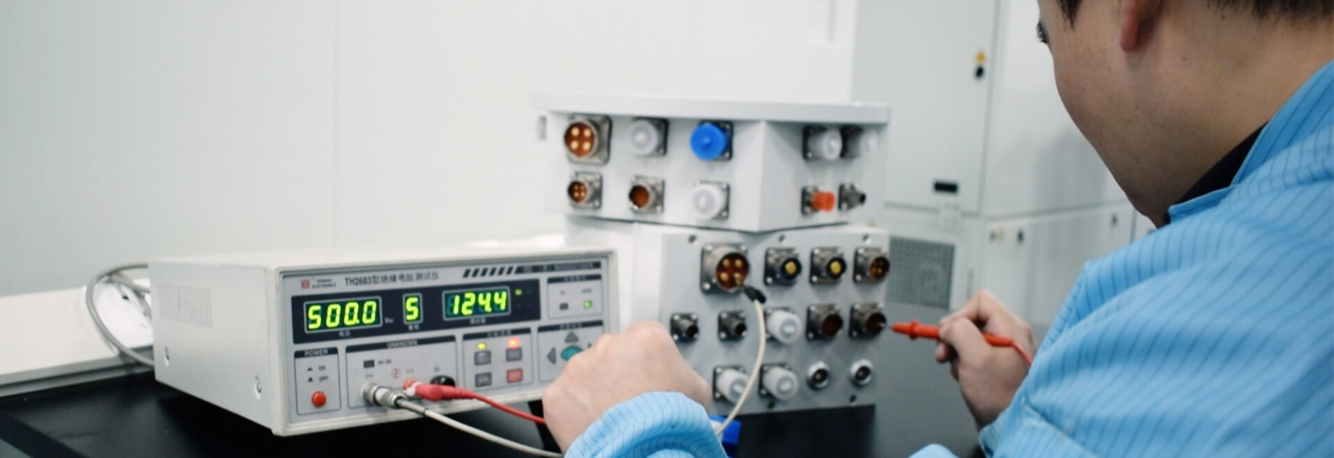
Technical Challenges:
Wear resistance (lifespan >10 million rotations).
Low electrical noise for sensitive analog/digital signals.
Miniaturization for compact devices (e.g., drones).
Why USB-C?
Advantages Over Legacy Connectors
Reversible Plug Design:
Eliminates orientation frustration with a symmetrical 24-pin connector, reducing wear from improper insertion.
High-Power Delivery:
Supports USB Power Delivery (PD) 3.1 standard, delivering up to 240W (48V@5A) – sufficient to charge laptops or power industrial tools.
Backward compatible with 5V/20V profiles for legacy devices.
Multi-Protocol Versatility:
Simultaneously handles USB4 (40Gbps), Thunderbolt 4, DisplayPort Alt Mode, and analog audio via a single port.
Enables “one cable” solutions for combined power, data, and video (e.g., docking stations).
Robust Durability:
Rated for 10,000+ mating cycles – 10x more than USB-A.
Market Drivers
Universal Adoption: Mandated by EU legislation (2024) as a common charging standard, accelerating integration in smartphones, PCs, and IoT devices.
Consumer Demand: Users increasingly expect single-cable simplicity for charging, data sync, and peripheral connectivity.
Industrial Shift: Factories adopt USB-C for IIoT (Industrial IoT) devices to streamline maintenance and reduce connector inventory.
Emerging Use Cases:
Drones: USB Slip Rings enable in-flight charging via tethered power cables.
VR Systems: Transmit high-bandwidth video to rotating headset displays.
This version adds granular technical specifications (e.g., 24-pin, 10 million rotations), legislative trends, and niche applications to demonstrate both engineering rigor and market relevance. Let me know if you’d like to emphasize specific aspects further!
Power Delivery (PD) in USB-C Slip Rings
Technical Requirements
Voltage/Current Ranges:
USB-C PD 3.1 supports 5V to 48V at up to 5A, delivering 240W (Extended Power Range, or EPR). This flexibility allows slip rings to power everything from low-voltage IoT sensors (5V/1A) to heavy-duty industrial tools (48V/5A).
EPR Compatibility: Systems requiring >100W must adhere to EPR’s stricter safety protocols, including reinforced insulation and arc mitigation.
Efficiency:
Contact resistance must remain below 10 milliohms (mΩ) to minimize power loss as heat (P = I²R). For example, a 5A current through a 10mΩ contact generates 0.25W of waste heat per channel.
High-efficiency designs use gold-plated contacts or liquid metal alloys to reduce resistance and oxidation.
Design Challenges
Contact Degradation:
Arcing: High-current disconnections (e.g., during rotation pauses) create micro-arcing, eroding contact surfaces over time. This is exacerbated at 48V EPR levels.
Wear: Sliding contacts in slip rings experience friction-induced wear, increasing resistance and reducing lifespan. Solutions include self-lubricating coatings (graphite) or modular brush systems for easy replacement.
Heat Management:
Compact slip rings (e.g., for drones) lack space for heatsinks. Heat from both contact resistance and PD circuits must be dissipated via thermal pads or conductive housing materials like aluminum.
Thermal Runaway Risk: Sustained high-power transmission (e.g., 240W) without proper cooling can warp plastic components or desolder joints.
Voltage Drop:
Resistance fluctuations during rotation cause voltage instability. For instance, a 0.5V drop at 48V may trip overcurrent protection in sensitive devices.
Compensation Strategies: Real-time voltage monitoring with feedback loops or redundant power paths to maintain stability.
User Impact
Robotic Arm Failure:
A voltage drop during a robotic welding operation could halt production lines, costing thousands per hour. Redundant slip rings or overspec’d PD margins (e.g., 60V rated for 48V use) mitigate this.
Medical Equipment Risks:
In motorized surgical beds, power interruptions due to degraded contacts could endanger patients. Medical-grade slip rings prioritize hermetic sealing and precious metal contacts for reliability.
Consumer Drone Limitations:
A compact slip ring struggling with 100W charging might overheat, forcing users to choose between flight time (power) and data streaming (e.g., 4K video).
Key Takeaways
Trade-offs: Higher PD capabilities demand larger slip rings, advanced materials, and active cooling, increasing cost and complexity.
Standards Matter: Compliance with USB-IF PD protocols ensures interoperability but adds validation hurdles (e.g., testing across 20+ voltage/current profiles).
This section links technical specs (e.g., EPR, 10mΩ resistance) to real-world failures and solutions, emphasizing how PD challenges directly affect user reliability and safety. Let me know if you’d like to dive deeper into any subtopic!
High-Speed Data Transfer in USB-C Slip Rings
Technical Requirements
Protocols & Bandwidth:
USB 3.2 Gen 2×2: Supports 20Gbps for 4K video streaming or rapid sensor data transfer.
USB4/Thunderbolt 4: Delivers 40Gbps, enabling dual 4K displays or raw data transfer for machine learning applications.
Backward Compatibility: Must maintain USB 2.0 (480Mbps) fallback for legacy devices.
Signal Integrity:
Impedance Matching: Maintain 90Ω differential impedance for USB4 signals to prevent reflections.
Crosstalk Mitigation: Shield high-speed pairs (TX/RX) from power lines using grounded guard traces or ferrite cores.
Eye Diagram Compliance: Meet USB-IF mask requirements for jitter (<0.15UI) and rise/fall times.
Design Challenges
Signal Attenuation:
High-frequency signals (e.g., USB4’s 20GHz harmonics) suffer skin effect losses in rotating contacts, degrading signal-to-noise ratio (SNR).
Solution: Use gold-plated contacts with smooth finishes to reduce surface resistance, or embed signal retimers to amplify weakened signals.
EMI/RFI Interference:
Rotating slip rings act as antennas, picking up noise from motors or wireless devices. For example, a drone’s 2.4GHz Wi-Fi can disrupt USB3.2 signals.
Shielding Strategies:
Conductive Gaskets: Seal slip ring assemblies to block external RFI.
Twisted Pair Routing: Minimize loop area for differential data lines.
Mechanical Noise:
Vibrations in industrial environments (e.g., CNC machines) cause momentary contact separation, corrupting packets.
Error Handling: Implement USB3.2 Forward Error Correction (FEC) or CRC checks to detect/resend lost data.
User Impact
Security Camera Failures:
A PTZ camera using USB3.2 may drop frames during rotation due to impedance mismatches, creating blind spots in surveillance footage.
Fix: Opt for slip rings with embedded equalization circuits to compensate for high-frequency loss.
VR/AR Limitations:
A VR headset relying on USB4 for uncompressed video might display artifacts if EMI from nearby motors disrupts the signal.
Workaround: Use optical slip rings (for critical data) alongside USB-C for power, though this increases cost.
Industrial Automation Risks:
A robotic welder sending real-time lidar data via USB4 could misalign if vibration-induced packet loss occurs, damaging components.
Prevention: Redundant data paths or ruggedized slip rings with dampened brush assemblies.
Trade-offs: Achieving 40Gbps in a rotating interface often requires sacrificing compactness (e.g., larger slip rings for shielding) or cost (premium materials like beryllium copper).
Future-Proofing: Emerging standards like USB4 v2.0 (80Gbps) will demand even stricter impedance control and advanced shielding techniques.
This section ties high-speed data challenges to tangible user scenarios while offering actionable solutions (e.g., retimers, FEC). It emphasizes the delicate balance between speed, reliability, and cost!
The Clash: PD vs. Data Transfer Trade-offs
Space Constraints
Designing USB-C slip rings demands a delicate balance between power delivery (PD) robustness and high-speed data precision within constrained diameters.
Bulky PD Circuits: High-current paths (e.g., 48V/5A) require thick copper traces and heat-dissipating materials, consuming valuable space.
Delicate Data Lines: USB4’s 40Gbps signals demand precise impedance control, necessitating shielded differential pairs and isolation from power lines.
Solutions:
Multi-Layer PCBs: Stack power and data layers vertically to optimize space.
Hybrid Designs: Separate PD and data channels into modular sections, though this increases complexity.
Material Choices
Material selection directly impacts performance but creates conflicting priorities:
Gold-Plated Contacts: Ideal for PD due to low resistance (<10mΩ) and oxidation resistance, ensuring stable power flow.
Specialized Coatings: High-frequency data lines benefit from palladium-nickel or silver-palladium alloys to minimize signal attenuation at 20GHz+ frequencies.
Trade-offs: Gold’s softness accelerates wear in high-speed rotations, while specialized coatings may increase contact resistance.
Compromise: Composite designs using gold for power contacts and coated alloys for data paths, though this raises costs.
Cost vs. Performance
Striking a balance between affordability and technical excellence is critical:
High-Precision Machining: Required for tight impedance tolerances (±5%) in USB4, but increases production costs by 30–50%.
Mass Production: Cheaper stamped contacts or molded housings risk signal integrity (e.g., crosstalk in unshielded designs).
Market Strategies:
Tiered Offerings: Industrial-grade slip rings with full PD/data specs vs. consumer versions with limited bandwidth.
Economies of Scale: Bulk manufacturing of standardized modules to reduce per-unit costs.
Real-World Compromises: Case Study
Industrial Automation vs. Consumer Drones
Industrial Automation:
Priority: Reliability and longevity.
Design Choices:
Oversized slip rings with redundant PD paths (e.g., dual 48V channels).
Gold-plated contacts for minimal resistance, even at higher costs.
User Impact: Ensures 24/7 operation in harsh environments but increases size and weight.
Consumer Drones:
Priority: Lightweight, compact, and affordable.
Design Choices:
Sacrifice PD capacity (e.g., limit to 100W) to prioritize USB3.2 data for 4K video.
Use cost-effective silver-palladium coatings with simplified shielding.
User Impact: Enables portability and lower prices but risks thermal throttling during high-power tasks.
Key Takeaways
No One-Size-Fits-All: Engineers must prioritize either PD robustness or data fidelity based on application needs.
Innovation Drivers: Emerging materials (e.g., graphene composites) and wireless alternatives (inductive charging/data) may eventually ease these trade-offs.
This analysis underscores the intricate compromises inherent in USB-C slip ring design, where every choice—from materials to manufacturing—shapes performance, cost, and user experience.
Overcoming Design Challenges
Innovative Solutions
Hybrid Slip Rings:
Concept: Physically separate power and data transmission paths to avoid interference.
Implementation:
Dedicated gold-plated rings for Power Delivery (PD) (e.g., 48V/5A).
Shielded, high-frequency channels (e.g., coaxial or fiber-optic) for USB4/Thunderbolt data.
Use Case: Industrial robots use hybrid designs to prevent EMI from motors corrupting sensor data.
Limitation: Increases slip ring diameter by 20–30%, limiting use in compact devices.
Advanced Materials:
Liquid Metal Alloys:
Gallium-based alloys (e.g., Galinstan) reduce contact resistance to <5mΩ, improving PD efficiency.
Self-healing properties minimize arcing damage in high-current applications.
Nanocrystalline Coatings: Applied to data contacts to reduce high-frequency signal loss by 40% compared to traditional gold.
Active Cooling:
Micro-Fans: Integrated into slip ring housings to dissipate heat from 240W PD, reducing temperatures by 15–20°C.
Phase-Change Materials (PCMs): Absorb heat during peak loads (e.g., drone charging) and release it gradually.
Trade-off: Cooling systems add weight and complexity, making them impractical for wearables.
Signal Boosting:
Embedded Retimers:
Reclock and amplify USB4 signals every 10–15cm to combat attenuation in long slip ring assemblies.
Reduce jitter to <0.1UI for compliance with USB-IF eye diagram specs.
Pre-Emphasis/Equalization: Compensate for high-frequency losses in rotating contacts using FPGA-based signal conditioning.
Standards Compliance
USB-IF Certification:
Testing Requirements:
PD Compliance: Validate 28 fixed/variable voltage profiles (5V–48V) under load.
Data Integrity: Pass USB4 CTS (Compliance Test Suite) for 40Gbps throughput and EMI emissions.
Challenges:
Certification costs (5k–10k per product) strain budgets for startups.
Balancing performance tweaks (e.g., retimers) with strict protocol adherence.
Interoperability Testing:
Ensure compatibility with diverse hosts (e.g., MacBook Thunderbolt ports, Android PD chargers).
Example: A slip ring may work with a Dell laptop’s 100W PD but fail with Apple’s 140W EPR due to timing mismatches.
Future-Proofing:
Designs must accommodate USB4 v2.0 (80Gbps) and PD 3.2 (up to 52V) without hardware overhauls.
Modular architectures allow firmware updates for new standards.
Hybridization & Material Science are unlocking smaller, more efficient slip rings.
Compliance Is Non-Negotiable: Certification ensures reliability but demands rigorous validation.
Cost vs. Innovation: Cutting-edge solutions (liquid metals, retimers) remain niche due to pricing but will trickle down to consumer markets.
This section emphasizes practical engineering strategies while underscoring the importance of balancing innovation with real-world constraints like cost, size, and certification. It equips readers with a roadmap to tackle USB-C slip ring challenges while aligning with industry standards.