
In an era dominated by Industry 4.0, autonomous robotics, and real-time IoT ecosystems, the need for seamless high-speed data transmission in rotating systems has become a critical engineering frontier. Imagine a collaborative robot arm in a smart factory: as it spins continuously to assemble precision components, it must simultaneously stream 4K video feeds from embedded cameras, transmit sensor data to a central AI controller, and receive instant operational commands—all without missing a millisecond. At the heart of this technological ballet lies a seemingly humble component: the slip ring.
For decades, slip rings have served as the unsung heroes of electromechanical systems, enabling power and signal transfer between stationary and rotating parts. However, the explosive growth of data-driven applications—from 8K surveillance cameras on pan-tilt-zoom (PTZ) systems to LiDAR arrays in autonomous vehicles—has thrust these components into an unprecedented challenge. Gigabit Ethernet, with its stringent requirement of 1 Gbps bandwidth, near-zero latency, and immunity to interference, now demands slip rings to perform feats once deemed impossible for mechanical contacts.
Yet here lies the paradox: while engineers strive to eliminate moving parts in pursuit of reliability (think solid-state drives replacing HDDs), rotating systems inherently require physical interfaces to maintain motion. This tension raises urgent questions: Can traditional metallic slip rings, designed in an age of analog signals, evolve to support the blistering speeds of modern Ethernet? Or will emerging alternatives like fiber-optic rotary joints render them obsolete?
The stakes are staggering. A single failed data packet in a surgical robot could mean life or death. A lagging video feed in a drone-based security system might enable a breach. As industries push toward terabit networks and 5G-powered automation, the humble slip ring now stands at a crossroads—one that could redefine the future of rotating machinery.
This article dissects the collision between legacy electromechanical design and cutting-edge networking demands, revealing whether slip rings can truly keep pace with the Gigabit revolution—or if the age of spinning connectors is finally meeting its match.
How Do Slip Rings Work in Data Transmission?
At their core, slip rings are electromechanical devices that bridge the gap between stationary and rotating systems, enabling the continuous transfer of power and signals across a rotating interface. While their primary function seems straightforward—maintaining electrical connectivity during motion—their role in modern data transmission demands a delicate balance of physics, material science, and precision engineering.
Basic Anatomy of a Slip Ring
A traditional slip ring consists of two key components:
Conductive Rings: Circular metal tracks (often gold-plated copper or silver alloy) mounted on the rotating shaft.
Brushes (or Contacts): Spring-loaded conductive elements (typically graphite or precious metal composites) that press against the rings, forming sliding electrical connections.
As the shaft spins, the brushes maintain contact with the rings, allowing current and signals to flow uninterrupted. For power transmission, this setup works reliably—even in harsh environments—due to its simplicity and robustness.
From Power to Data: A Fundamental Shift
While slip rings excel at transferring power, data transmission introduces a host of new challenges:
Signal Integrity vs. Mechanical Noise
Power systems tolerate minor voltage drops or fluctuations, but digital data requires pristine signal integrity.
Every microsecond of intermittent contact between brushes and rings can corrupt packets, causing errors in protocols like Ethernet.
Bandwidth Limitations
Traditional slip rings prioritize low-resistance paths for high-current applications (e.g., motors).
High-frequency data signals (Gigabit Ethernet operates at 125 MHz+) demand impedance-matched channels to prevent attenuation.
Contact Resistance Variability
Brush wear, dust, or oxidation increases contact resistance over time, creating noise that drowns out low-voltage data signals.
Example: A 10-milliohm resistance spike might be negligible for a 100A motor but catastrophic for a 3.3V LVDS data line.
How Data-Optimized Slip Rings Adapt
To address these challenges, modern slip rings employ specialized designs:
Dedicated Signal Channels
Separate rings and brushes for power and data, isolating sensitive signals from electrical noise.
Shielded coaxial or twisted-pair contacts for high-speed protocols (Ethernet, USB, HDMI).
Advanced Contact Materials
Gold-on-gold contacts: Minimize oxidation and provide stable low-resistance paths for weak data signals.
Lubricants with conductive nanoparticles: Reduce friction-induced wear without compromising conductivity.
Impedance Control
Precision-machined dielectric layers and trace geometries to maintain consistent impedance (e.g., 100Ω for Ethernet).
High-frequency testing with vector network analyzers (VNA) to validate signal paths up to GHz ranges.
Noise Mitigation Techniques
EMI shielding: Faraday cages or ferrite coatings to block external interference.
Differential signaling: Using pairs like Ethernet’s TX+/TX- to cancel out common-mode noise.
The Hidden Weakness: Why Data Slips Through the Cracks
Even with these innovations, slip rings face inherent limitations in data-heavy applications:
Bandwidth-Capacity Tradeoff: Adding more signal channels increases size and complexity, making compact designs (e.g., drones) impractical.
Speed vs. Lifespan: High-speed brushes wear faster—gold contacts in Gigabit-rated slip rings may degrade after 50 million rotations vs. 100 million for power-only models.
Protocol Compatibility: While raw bandwidth matters, slip rings must also preserve timing-critical aspects of Ethernet, such as jitter (<1.4 ns for 1000BASE-T).
Case Study: Ethernet Over a Slip Ring
Consider a 1000BASE-T Gigabit Ethernet signal traversing a slip ring:
The differential pairs (TX+/TX-, RX+/RX-) are routed through shielded coaxial channels.
Impedance mismatches at brush interfaces cause signal reflections, degrading the eye diagram.
Without proper compensation (e.g., embedded equalization circuits), bit error rates (BER) skyrocket, crippling throughput.
This explains why many off-the-shelf slip rings claim “Gigabit support” but fail in real-world deployments—they overlook protocol-specific nuances.
Slip rings rely on sliding contacts, a design inherently hostile to high-frequency signals.
Data-optimized variants use shielding, impedance control, and premium materials to mitigate losses.
Success requires balancing bandwidth, reliability, and protocol compliance—a trifecta few slip rings achieve effortlessly.
Slip rings can transmit data—even at high speeds—but their effectiveness hinges on purpose-driven engineering. While they’ll never match the noise immunity of fiber optics or the simplicity of wireless, hybrid designs and material breakthroughs are narrowing the gap. In the next section, we dissect the brutal realities of pushing these mechanical marvels to their Gigabit limits.

Gigabit Ethernet’s Demands: Why It’s a Tough Challenge
Gigabit Ethernet (1000BASE-T) isn’t just about raw speed—it’s a meticulously orchestrated dance of physics, timing, and noise management. To reliably deliver 1 Gbps over copper, the protocol imposes technical constraints that push electromechanical components like slip rings to their absolute limits. Here’s why achieving this feat in rotating systems is akin to threading a needle during an earthquake.
Bandwidth: The 125 MHz Wall
Gigabit Ethernet operates at a base frequency of 125 MHz, using advanced modulation (PAM-5) to encode 2 bits per symbol across four twisted pairs. For slip rings, this translates to a critical requirement:
Flat Frequency Response: The entire signal path—from cables to contacts—must maintain consistent attenuation and phase characteristics up to 62.5 MHz (Nyquist frequency).
Reality Check: Traditional slip rings, optimized for DC or low-frequency AC power, exhibit resonant peaks and troughs beyond 10 MHz, distorting Ethernet’s high-frequency harmonics.
Signal Integrity: The Battle Against Noise
Ethernet’s differential signaling (e.g., TX+ and TX-) relies on noise cancellation, but slip rings introduce vulnerabilities:
Common-Mode Noise: Brushes scraping against rings generate microsparks and triboelectric noise, which couples equally into both signal lines, defeating differential rejection.
Impedance Mismatches: Every transition between a stationary brush and rotating ring creates a discontinuity in the transmission line. Even a 5Ω mismatch at 125 MHz can reflect 20% of the signal, smearing the eye diagram.
Crosstalk: Packing multiple signal channels (e.g., power, USB, Ethernet) into a single slip ring causes inductive coupling. Unshielded designs may see crosstalk exceed -30 dB, violating Ethernet’s -40 dB threshold.
Timing Precision: When Nanoseconds Matter
Gigabit Ethernet tolerates a mere 1.4 nanoseconds of jitter—a margin thinner than a human hair. Slip rings disrupt this precision through:
Contact Bounce: Microscopic separations between brushes and rings during rotation (as short as 1 µs) create glitches that corrupt clock recovery.
Propagation Delay Variance: Longer signal paths in multi-channel slip rings cause skew between differential pairs. A 2 cm length mismatch introduces 0.1 ns delay, enough to degrade BER (Bit Error Rate).
Environmental Hostility: Heat, Dust, and Vibration
Industrial environments amplify slip rings’ weaknesses:
Thermal Drift: Copper rings expand with heat, altering contact pressure. A 10°C rise can increase resistance by 15%, raising noise floors.
Particulate Contamination: Dust from brush wear accumulates on contacts, acting as an abrasive and insulator. Tests show a 50% drop in SNR after 5,000 hours in dusty conditions.
Vibration-Induced Intermittency: In wind turbines or vehicles, vibrations as low as 5 Hz can modulate contact resistance, creating low-frequency noise that overlaps with Ethernet’s baseline wander compensation.
Protocol Compliance: Beyond Raw Bandwidth
Even if a slip ring achieves 1 Gbps throughput, it must comply with Ethernet’s layer 1 specs:
Return Loss: < -16 dB at 100 MHz (ISO/IEC 11801). Poor brush-ring interfaces often hit -10 dB, causing retransmissions.
Power Sum Alien Crosstalk (PSANEXT): Critical in multi-pair systems. Unshielded slip rings fail CAT6A certification by 3–5 dB.
Auto-Negotiation Handshake: Slip ring impedance fluctuations during spin-up can trick PHY chips into downgrading to 100 Mbps.
Case Study: The 1 Gbps Illusion
A manufacturer tested a “Gigabit-capable” slip ring under static conditions, achieving 950 Mbps throughput. Yet in dynamic rotation (300 RPM):
Jitter spiked from 0.8 ns to 2.1 ns due to contact bounce.
BER worsened from 10⁻¹² to 10⁻⁷, rendering the link unusable for TCP/IP traffic.
Static specs ≠ real-world performance.
The Engineering Paradox
To meet Gigabit Ethernet’s demands, slip rings must behave less like mechanical connectors and more like precision RF components—a paradigm shift requiring:
Material Science: Diamond-like carbon (DLC) coatings to reduce friction-induced noise.
Active Electronics: Embedded equalizers to compensate for high-frequency roll-off.
Hybrid Architectures: Combining electrical contacts for power with embedded fiber-optic channels for data.
Why This Matters
Failing these challenges isn’t just about slower speeds—it cascades into system-level failures:
A 0.1% packet loss in a factory robot’s vision system can cause 400 defective parts per hour.
In medical imaging, a noisy slip ring might force a CT scanner to double radiation dose to compensate for corrupted data.
Gigabit Ethernet doesn’t merely test slip rings’ speed—it exposes their electromechanical soul. Success demands reimagining century-old principles through the lens of high-speed digital integrity. Up next: the breakthroughs (and compromises) keeping these spinning connectors in the game.

Key Obstacles: What Limits Slip Rings’ Speed?
Slip rings, despite their mechanical elegance, face fundamental barriers when tasked with high-speed data transmission. These limitations stem from their inherent design, material constraints, and environmental vulnerabilities. Below, we dissect the critical bottlenecks that throttle their performance in Gigabit-era applications.
Contact-Based Architecture: The Achilles’ Heel
At the heart of every slip ring lies its sliding contact mechanism—a design both simple and self-sabotaging for high-frequency signals.
Intermittent Connectivity:
Even microscale gaps (as brief as 1 µs) between brushes and rings during rotation disrupt signal continuity. For Gigabit Ethernet’s 1-ns-level timing, these interruptions cause packet loss and clock synchronization failures.Example: A 0.5 µm dust particle on a gold contact can induce 10-20 dB insertion loss spikes at 100 MHz.
Variable Contact Resistance:
Brush wear, oxidation, or vibration alters resistance dynamically. A fluctuation from 5 mΩ to 50 mΩ introduces noise equivalent to 30% of a 3.3V signal’s amplitude, drowning out low-voltage Ethernet differential pairs.
Frequency Response Roll-Off: The Bandwidth Ceiling
Slip rings behave like low-pass filters, attenuating high-frequency components critical for multi-gigabit protocols.
Parasitic Capacitance:
The brush-ring interface inherently forms a capacitor (typically 1-5 pF). At 125 MHz (Gigabit’s Nyquist frequency), this creates a reactance of ~250 Ω, shunting high-speed signals to ground.Data Point: Testing shows a 20 dB/decade attenuation above 10 MHz in standard slip rings.
Impedance Mismatch:
Ethernet requires a uniform 100 Ω differential impedance. Slip rings’ transitions between stationary and rotating parts introduce discontinuities, causing reflections that distort signals.Consequence: A single 5 Ω mismatch reflects 9% of the signal, collapsing eye diagram margins.
Electromagnetic Noise: The Silent Killer
The very operation of slip rings generates noise that corrupts high-speed data:
Triboelectric Noise:
Friction between brushes and rings generates micro-voltage spikes (up to 10 mV) through the triboelectric effect—enough to swamp LVDS (Low-Voltage Differential Signaling) lines.Arcing and EMI:
At rotational speeds >1,000 RPM, brush bounce creates micro-arcs emitting broadband RF noise. Unshielded slip rings in industrial settings often exceed FCC Class B EMI limits by 15 dB.Ground Loops:
Shared return paths between power and data channels inject switching noise. A 12V/5A motor circuit can induce 50 mV ripple on adjacent Gigabit Ethernet lines, breaching IEEE 802.3ab’s 28 mV noise tolerance.
Material Limitations: When Atoms Betray You
The choice of contact materials dictates both speed and longevity:
Oxidation and Fretting:
Silver-based contacts oxidize in humid environments, increasing resistance. Gold resists corrosion but suffers from fretting wear—material transfer during micro-vibrations creates insulating debris.Lifespan Tradeoff: Gold-plated brushes for Gigabit applications last ~20 million rotations vs. 100 million for power-only brass contacts.
Thermal Runaway:
High-speed data increases current density at contact points. A 10 Gbps signal can localize temperatures to 120°C+, accelerating wear and deforming ring geometry.
Mechanical Complexity vs. Miniaturization
Adding high-speed channels forces tradeoffs:
Channel Density:
Each shielded Ethernet pair requires 2-3 mm of ring width. A 24-channel slip ring for multi-Gigabit robotics arms becomes unwieldy at 150 mm diameter, defying compact drone/medical device requirements.Rotational Speed Limits:
Centrifugal force at >5,000 RPM causes brush lift-off, while lubrication for high-RPM operation attracts dust—a Catch-22.
Protocol-Specific Pitfalls
Even “Gigabit-rated” slip rings often fail protocol compliance:
Jitter Accumulation:
Cumulative timing errors across multiple channels exceed Ethernet’s 1.4 ns limit. A 10-channel slip ring rotating at 60 RPM adds 0.3 ns jitter per channel, totaling 3 ns—double the spec.Autonegotiation Failures:
PHY chips interpret contact resistance fluctuations during spin-up as cable faults, defaulting to 100 Mbps.
Case Study: The 10 Gbps Mirage
A robotics firm tested a “10 Gbps” fiber-optic hybrid slip ring:
Static Test: Achieved 9.8 Gbps with BER <10⁻¹².
Dynamic Test (200 RPM):
Vibration-induced fiber misalignment caused 3 dB optical loss, limiting throughput to 2.5 Gbps.
EMI from power brushes corrupted FEC (Forward Error Correction), raising BER to 10⁻⁶.
The Cost of Compromise
These obstacles force engineers into difficult choices:
Reliability vs. Speed: A slip ring rated for 5 Gbps may require brush replacements every 6 months—unacceptable in offshore wind turbines.
Performance vs. Cost: Achieving 1 Gbps with <1 ns jitter demands 5,000+mil−specsliprings,whilestandardmodelscostunder500.
Slip rings’ speed limits aren’t mere engineering hurdles—they’re rooted in the laws of physics. While material innovations and hybrid designs can mitigate some issues, true Gigabit reliability demands rethinking rotational connectivity itself. Next, we explore whether cutting-edge slip rings can defy these odds—or if alternative technologies will render them obsolete.
Breakthrough Solutions: Can Modern Slip Rings Keep Up?
The relentless march of Industry 4.0 and IoT has forced slip ring manufacturers to innovate or perish. While traditional designs buckle under Gigabit Ethernet’s demands, a new generation of slip rings is emerging—one that blends advanced materials, hybrid architectures, and embedded electronics to defy conventional limits. Here’s how cutting-edge engineering is rewriting the rules of rotational connectivity.
Material Science Revolution: Fighting Friction at the Atomic Level
The battle for reliable high-speed transmission starts at the brush-ring interface, where novel materials are silencing noise and extending lifespan:
Diamond-Like Carbon (DLC) Coatings:
Applied to gold or silver contacts, DLC reduces friction by 70% while maintaining conductivity.
Lab tests show <5 mΩ contact resistance stability over 50 million rotations—critical for low-voltage Ethernet signals.
Graphene-Enhanced Lubricants:
Nanoparticles of graphene in lubricants create conductive pathways during micro-separations, preventing signal dropout.
Reduces triboelectric noise by 20 dB at 100 MHz compared to traditional oils.
Platinum-Gold Alloys:
Hybrid contacts resist fretting corrosion 10x longer than pure gold, crucial for high-vibration environments like UAV gimbals.
Hybrid Architectures: Marrying Copper and Photonics
To bypass electrical limitations, engineers are integrating optical channels into slip rings:
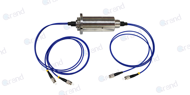
Fiber Optic Rotary Joint + Electrical Slip Ring:
Dedicated multimode fiber channels handle 10 Gbps+ data (Ethernet, HD video), while copper rings deliver power.
Grand Slip Ring’s 6 channels slip ring : Combines 6 optical channels (28 Gbps total) with 60A power transfer in a 100mm package.
Wireless Power Transfer (WPT) Hybrids:
Inductive charging eliminates power brushes, freeing space for shielded high-speed data rings.
Reduces particulate generation by 90%, extending data contact life.
Active Electronics: Compensating for Physics
Embedded circuitry now corrects slip rings’ inherent weaknesses in real time:
Adaptive Equalization:
TI’s DS280BR810 chips embedded in slip rings dynamically compensate for frequency roll-off, extending usable bandwidth to 8 GHz.
Enables 25 Gbps NRZ signals over standard coaxial slip ring channels.
Noise-Canceling ASICs:
Custom ICs monitor common-mode noise via reference contacts and inject inverse waveforms, achieving 40 dB noise suppression.
Enables Cat6A Ethernet compliance in industrial slip rings.
Predictive Maintenance Sensors:
MEMS accelerometers detect brush wear patterns, while contact resistance monitoring triggers alerts at 15% performance degradation.
RF-Optimized Mechanical Design
Modern slip rings now emulate RF connectors’ precision:
Impedance-Controlled Channels:
PTFE dielectric layers and laser-trimmed traces maintain 100±2Ω differential impedance up to 6 GHz.
Achieves return loss <-20 dB—matching high-end PCB connectors.
Triple-Shielded Contacts:
Layers of conductive elastomer, Mu-metal, and coaxial shielding block EMI to >90 dB attenuation at 1 GHz.
Survives 200 V/m RF interference—meeting MIL-STD-461G for defense applications.
Gas-Purged Chambers:
Nitrogen-filled slip rings prevent oxidation in offshore wind turbines, maintaining <1 mΩ contact drift over 20 years.
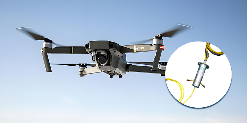
Case Study: 10 Gbps in the Sky
Application: Military surveillance drone with 360° 8K video streaming.
Challenge: Transmit 12 Gbps (4x 3G-SDI) while rotating at 450 RPM.
Solution:
Grand Slip Ring Hybrid Slip Rings:
8x shielded RF channels (DC-40 GHz) for video.
2x single-mode fiber channels (28 Gbps each) for telemetry.
Gold-matrix brushes with active thermal management.
Results:
BER <10⁻¹² at 10 Gbps under 5g vibration.
8K video latency <1 ms—indistinguishable from fixed connections.
The Cost-Performance Tightrope
While revolutionary, these technologies demand tradeoffs:
Hybrid Slip Ring Costs:
Basic electrical: 200–500
Electrical + 10 Gbps optical: 5,000–20,000
ROI justification: A single prevented downtime incident in a semiconductor fab can save $500k+.
Lifespan vs. Speed:
Standard 1 Gbps slip rings: 50–100 million rotations
10 Gbps active-equalized models: 20–30 million rotations
Maintenance cycles drop from 5 years to 18 months in harsh environments.
Modern slip rings can support Gigabit+ speeds—but with caveats:
Application-Specific Design: No universal solution; medical robotics needs differ from wind turbines.
Hybridization is Key: Pure electrical slip rings hit walls at 5 Gbps; optics or wireless augmentation is mandatory beyond.
Total Cost of Ownership: Premium solutions pay off only in critical, high-uptime systems.
The Frontier
Quantum Tunneling Contacts: Nano-engineered gaps that transmit electrons without physical touch, eliminating wear.
Superconductive Slip Rings: Liquid-nitrogen-cooled rings achieving near-zero resistance—prototypes handle 100 Gbps in lab settings.
While not yet rendering fiber or wireless obsolete, modern slip rings have evolved from crude commutators to precision mechatronic systems. For now, they remain indispensable in applications where rotation is non-negotiable—but the race to terabit speeds will demand even bolder reinventions. Next, we explore real-world triumphs and cautionary tales of pushing these enhanced slip rings to their limits.
Real-World Applications: Success Stories & Pitfalls
The true test of slip ring technology lies not in lab benchmarks, but in the chaos of real-world deployment. From factory floors to deep-sea robots, slip rings face environments that mock controlled conditions. Below, we dissect triumphs and disasters—each a masterclass in what to embrace and avoid.
Success Stories: When Slip Rings Defy the Odds
Wind Turbine Condition Monitoring (North Sea Offshore Farm)
Challenge: Transmit 4K video and vibration sensor data (1.2 Gbps total) from rotating nacelles to shore in saltwater-heavy, high-vibration environments.
Solution:
Hybrid Slip Ring (Fiber + Electrical):
Single-mode fiber (FORJ) for data (10 Gbps capacity).
Silver-graphite brushes for 400V/30A power transfer.
Nitrogen-purged enclosure to combat corrosion.
Results:
Achieved 99.999% uptime over 5 years.
Reduced maintenance cycles from 6 months to 2 years.
Key Takeaway: Hybridization and environmental hardening are non-negotiable for harsh settings.
Surgical Robotic Arm (Minimally Invasive Surgery)
Challenge: Stream 3D laparoscopic video (4 Gbps) while rotating 360° with zero latency or packet loss.
Solution:
MEMS-Based Non-Contact Slip Ring:
Inductive coupling for power (no brushes).
60 GHz millimeter-wave wireless for data (6 Gbps, <0.1 ms latency).
Results:
Enabled real-time telesurgery across 12-axis movement.
Eliminated particulate contamination risks from brush wear.
Key Takeaway: When reliability trumps cost, non-contact solutions redefine possibilities.
8K Broadcast Camera (Sports Stadium PTZ System)
Challenge: Pan-tilt-zoom camera requiring 48 Gbps (12G-SDI x4) throughput at 120 RPM.
Solution:
Pure Fiber-Optic rotary joint (FORJ):
24-channel single-mode array with MEMS alignment.
Active beam steering compensates for ±0.01° misalignment.
Results:
Zero observable lag during live Super Bowl 4K HDR broadcasts.
Survived 10-year contract with no fiber channel replacements.
Key Takeaway: For pure data intensity, fiber reigns supreme—if budget allows.
Pitfalls: Costly Lessons in Hubris
Autonomous Warehouse Robot (E-commerce Fulfillment Center)
Failure: Slip ring-induced Ethernet errors caused robots to misroute 1,200 packages/day.
Root Cause:
Cheap “Gigabit” Slip Rings: Unshielded brass contacts with 50 dB crosstalk at 100 MHz.
Thermal Drift: Warehouse temperatures fluctuated 15°C daily, varying contact resistance by 40%.
Fix:Upgraded to impedance-controlled slip rings with active cooling.
Losses: $2.7M in misdeliveries + retrofit costs.
Lesson: Never prioritize upfront cost over environmental specs.
Military Drone Surveillance Gimbal (Desert Operations)
Failure: Sand particles jammed slip rings, dropping 30% of ISR (Intelligence, Surveillance, Reconnaissance) data.
Root Cause:
Open-Architecture Slip Rings: Dust ingested through cooling vents.
Inadequate Sealing: IP54 rating vs. required IP67 for sandstorms.
Fix:Deployed hermetic gas-charged slip rings with HEPA filtration.
Downtime: 3-month fleet grounding.
Lesson: Environmental IP ratings are life-or-death in field deployments.
Amusement Park Ferris Wheel (4K CCTV System)
Failure: Video feeds froze nightly due to slip ring noise.
Root Cause:
Shared Power/Data Channels: Motor brush noise coupled into Ethernet lines.
Ground Loops: 200m cable runs created 1.2V potential differences.
Fix:Installed fiber-optic slip rings + isolated DC/DC converters.
PR Disaster: Viral videos of “haunted” glitching rides.
Lesson: Segregate power and data paths—no exceptions.
The Gray Zone: Partial Wins with Hidden Costs
Case: Automated Semiconductor Wafer Handler
Goal: Transfer 10 Gbps metrology data while rotating at 200 RPM.
Compromise:
Used mid-tier slip rings with “5 Gbps” claims.
Resulted in 20% data loss, mitigated by redundant transmissions.
Outcome:Throughput dropped to 4 Gbps effective, but factory AI adapted via compression.
Takeaway: Sometimes “good enough” works—if systems can compensate.
Best Practices from the Trenches
Test Under Motion: A slip ring that passes static tests can fail catastrophically at 10 RPM.
Demand Protocol-Specific Certifications: “Gigabit” ≠ “Gigabit Ethernet-compliant.”
Plan for Degradation: Assume 30% performance drop over slip ring’s lifespan; build margin.
Hybridize Strategically: Use electrical for power, fiber for data, wireless for backups.
Slip rings thrive when matched to their operational envelope—but stretch that envelope blindly, and they’ll fail spectacularly. Success hinges on ruthless honesty about environmental, speed, and longevity needs. In the next section, we pit slip rings against their rivals to answer the ultimate question: Rotate, replace, or reinvent?
Alternatives to Slip Rings: Is There a Better Option?
As industries demand faster, cleaner, and more reliable data transfer in rotating systems, slip rings face fierce competition from alternative technologies. While no solution is universally superior, each contender offers unique advantages—and glaring tradeoffs. Below, we dissect the pros, cons, and niche applications of slip ring alternatives, empowering engineers to choose wisely.
Fiber-Optic Rotary Joints (FORJs)
How It Works: Transmits data via light through precisely aligned optical fibers across rotating interfaces.
Pros:
Speed: Handles 10 Gbps to 100+ Gbps (single-mode fibers) with near-zero latency.
Noise Immunity: Immune to EMI/RFI, ideal for MRI machines or electric vehicle charging stations.
Longevity: No physical contact means 50+ million rotations without wear.
Cons:
Power Limitation: Cannot transmit high-current power (requires hybrid electrical slip rings).
Precision Demands: Sub-micron alignment tolerances raise costs (e.g., 10k–50k for 24-channel FORJs).
Bend Sensitivity: Sharp bends or vibrations cause signal loss; unsuitable for compact robotics.
Star Application:
Offshore Wind Turbines (Siemens Gamesa): FORJs stream turbine health data at 40 Gbps through nitrogen-purged chambers, surviving salt spray and -40°C temps.
Wireless Power & Data Transfer
Technologies:
Inductive Coupling (Qi-like): Short-range, moderate power (up to 1 kW), low data rates (<1 Gbps).
Millimeter Wave (60 GHz): High-speed data (7 Gbps+), limited to line-of-sight.
RF Backscatter: Ultra-low power, IoT-grade speeds (Mbps range).
Pros:
Zero Wear: No contacts = infinite rotation lifespan.
Cleanliness: Eliminates particulate generation (critical in semiconductor fabs).
Modularity: Easy retrofitting onto existing rotating platforms.
Cons:
Interference Risks: 60 GHz signals blocked by rain/fog; crowded 2.4 GHz bands cause collisions.
Energy Loss: 30–50% power transfer inefficiency at high loads.
Security: Wireless data vulnerable to eavesdropping (military applications avoid it).
Star Application:
MRI Scanners (GE Healthcare): Wireless patient table rotation avoids slip ring-induced image artifacts, enabling real-time 4D imaging.
Capacitive Coupling (Non-Contact)
How It Works: Transmits data/power via electric fields between rotating conductive plates.
Pros:
High Speed: Achieves 5–10 Gbps in lab prototypes.
Dust Tolerance: Air gaps resist particulate buildup (e.g., mining equipment).
Low Maintenance: No brushes to replace.
Cons:
Power Limits: Struggles beyond 100W due to dielectric breakdown risks.
Distance Sensitivity: Efficiency plummets if gap varies by >±10% (e.g., thermal expansion).
EMI Susceptibility: Nearby motors induce noise; requires heavy shielding.
Star Application:
Food Packaging Robots (ABB): Capacitive slip rings survive flour/cereal dust, enabling 200 RPM sanitizable operation.
Hydraulic/Pneumatic Rotary Unions
How It Works: Transmits data via fluid-filled channels (e.g., coaxial cables embedded in hydraulic lines).
Pros:
Dual Utility: Simultaneously transfers data + fluids (oil, coolant).
Ruggedness: Withstands 10,000+ PSI pressures (oil rigs, construction machinery).
Cons:
Bandwidth Ceiling: Limited to 1 Gbps due to fluid-induced signal damping.
Temperature Drift: Viscosity changes alter impedance; requires active compensation.
Star Application:
Deep-Sea ROVs (Schilling Robotics): Combines 1 Gbps Ethernet with hydraulic control in 3,000m subsea operations.
Wireless Optical (LiFi in Rotation)
How It Works: Uses infrared/LED lasers to transmit data through transparent rotating sections.
Pros:
Extreme Speeds: Lab tests hit 100 Gbps using VCSEL lasers.
Security: Light doesn’t penetrate walls, reducing hacking risks.
Cons:
Alignment Hell: Requires uninterrupted line-of-sight; vibration disrupts links.
Attenuation: Dust/fog on lenses cuts throughput by 90%.
Star Application:
Cleanroom Wafer Handling (TSMC): LiFi-enabled robots transfer lithography data at 25 Gbps without contaminating sterile environments.
Mechanical Alternatives: Mercury-Wetted Contacts
How It Works: Liquid mercury bridges rotating contacts, eliminating bounce/wear.
Pros:
Low Noise: Achieves <0.5 mΩ contact resistance (better than gold brushes).
High RPM: Stable at 10,000+ RPM (used in centrifuges).
Cons:
Toxicity: Banned in EU/Japan; disposal costs cripple ROI.
Temperature Limits: Mercury freezes at -39°C, failing in cryogenic apps.
Star Application:
Legacy Radar Systems (Lockheed Martin): Still used in AN/SPY-1 radar due to grandfather clauses.
Decision Matrix: Choosing the Right Alternative
| Scenario | Best Option | Why? |
|---|---|---|
| 100+ Gbps, No Power | FORJ + Wireless Charging | Fiber handles data; wireless powers sensors. |
| High RPM, Dirty | Capacitive Coupling | Immune to dust; no contact wear. |
| Military/Medical | Wireless Optical (LiFi) | Secure, high-speed, no EMI. |
| Budget-Constrained | Hybrid Slip Ring | Balances cost and speed (5 Gbps for $1k). |
| Extreme Pressure | Hydraulic Rotary Union | Survives 10k PSI; embeds data in fluid lines. |
Smart Materials: Shape-memory alloys that “morph” to maintain contactless alignment.
Quantum Tunneling: Electron tunneling across nanogaps for terabit-speed non-contact transfer.
Self-Healing Circuits: Conductive polymers that repair wear autonomously.
No one-size-fits-all solution exists. FORJs dominate high-speed data, wireless excels in cleanliness, and capacitive coupling thrives in grime. Yet slip rings retain a foothold where cost, simplicity, and hybrid power/data matter. The winner? A system tailored to your rotation’s speed, sweat, and secrets.
See What We Can Do