Computed Tomography (CT) scanners revolutionized medicine by providing detailed cross-sectional images of the human body. A critical, yet often overlooked, component enabling this technology’s speed and continuous rotation is the Slip Ring. Understanding its function and visualizing it through a Slip Ring Diagram is key to appreciating the engineering marvel behind modern CT scans.
The Problem: Continuous Rotation Needs Continuous Connections
The Gantry’s Challenge: The CT gantry houses the heavy, power-hungry X-ray tube (requiring 30-150 kV at significant current) and the highly sensitive detector array (generating gigabytes of data per second). To acquire data from all angles (360°+), this entire assembly must rotate continuously – often at speeds exceeding 3 rotations per second for cardiac CT.
The Cable Conundrum: Conventional fixed wiring would catastrophically tangle and snap within milliseconds of rotation starting. Stopping rotation after each slice acquisition (“stop-and-shoot” scanning) is prohibitively slow for dynamic organs (heart, lungs) and increases exam time/dose.
Core Requirements: The solution must simultaneously provide:
High-Power Transmission: Delivering kilowatts of stable electrical power to the X-ray tube under high voltage.
High-Speed Data Transmission: Relaying massive, high-fidelity digital data streams from the detectors with minimal latency and noise.
Control Signal Exchange: Sending control signals (e.g., tube activation timing, focal spot position, detector configuration) to the rotating components and receiving status signals back.
Continuous, Uninterrupted Operation: Supporting hours of continuous rotation at high speeds without degradation.
Compactness & Reliability: Operating within the confined gantry space under significant mechanical stress and thermal load.
The Solution: Introducing the Slip Ring (Expanded)
Fundamental Principle: An electromechanical device creating a continuous electrical connection between a stationary structure (Stator) and a rotating structure (Rotor) via sliding electrical contacts.
Core Functionality: Acts as a sophisticated, multi-channel, rotating electrical junction box. It multiplexes power, high-speed data, and control signals across the rotating interface.
Key Innovation Enabler: The slip ring is the sine qua non for helical/spiral CT scanning, allowing continuous gantry rotation while the patient table moves smoothly through the bore, enabling volumetric imaging in seconds.

Anatomy of a CT Scanner Slip Ring: Decoding the Diagram
Enabling Continuous Acquisition: The fundamental breakthrough allowing spiral CT scanning is slip ring technology in spiral CT. Before its adoption, restrictive cables forced CT gantries to stop, reverse rotation, and rewind after each complete rotation to avoid cable tangling, limiting scanning to discrete slices and causing motion artifacts. Slip ring technology in spiral CT replaces these cables with a system of rotating conductive rings and stationary brushes, enabling uninterrupted electrical contact for power and data transmission. This critical innovation permits the gantry to rotate continuously at high speed while the patient table moves smoothly through the bore, tracing the essential spiral (helical) X-ray path necessary for volumetric data acquisition.
A detailed CT Scanner Slip Ring Diagram reveals a complex electromechanical system. Let’s dissect each component:
Stationary Assembly (Stator):
Brushes (Electrical Contacts):
Material Science: Typically composed of precious metal alloys (e.g., silver-graphite, gold-palladium, or specialized copper alloys). These are chosen for low electrical resistance, high current-carrying capacity, low contact noise, and controlled wear characteristics. Graphite provides self-lubrication.
Design: Often shaped as rectangular blocks or multi-wire bundles (“fingers”). Spring-loaded to maintain constant, calibrated pressure (grams to kilograms force) against the rotating rings. Pressure is critical: too low causes arcing and signal dropout; too high causes excessive wear and heat.
Redundancy: Critical rings (e.g., HV, core data) use multiple brushes per ring, often staggered around the circumference. This ensures uninterrupted contact if one brush wears or lifts momentarily and distributes wear.
Brush Holders:
Precision Mechanics: Rigid structures precisely positioning the brushes relative to the rings. Incorporate mechanisms for brush spring force adjustment and often allow for easy brush replacement during maintenance.
Vibration Damping: May include features to minimize brush chatter or bounce induced by gantry vibration or imperfections in ring surfaces.
Stationary Wiring Harness:
High-Voltage (HV) Cabling: Heavy-duty, heavily insulated cables connecting the slip ring brushes to the High Voltage Power Supply (HVPS). Designed to handle tens of kilovolts.
Low-Voltage (LV) & Control Wiring: Standard or shielded cables for powering rotor electronics and control signals.
High-Speed Data Cabling: Shielded twisted pairs or coaxial cables connecting data brushes to the Data Acquisition System (DAS), often requiring impedance matching.
Cooling & Sensor Wiring: Connections for temperature sensors and potentially cooling system actuators.
Rotating Assembly (Rotor):
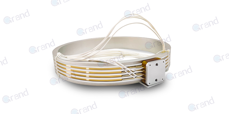
Conductive Rings:
Material & Fabrication: Typically precision-machined from high-conductivity copper alloys (e.g., beryllium copper for strength) or sometimes silver-plated copper. Mounted concentrically on an insulating cylinder.
Surface Finish: Highly polished to minimize friction and wear. May feature specialized platings (e.g., hard gold) in critical signal areas to reduce oxidation and contact resistance.
Isolation: Rings are separated by insulating spacers (often high-performance thermoset plastics like PEEK or polyimide, or ceramics). The spacing width is critical, especially for HV rings, to prevent arcing (creepage and clearance distances).
Ring Types: Dedicated rings exist for specific functions:
HV Anode/Cathode Rings: Thick, widely spaced.
LV Power Rings: For tube filament, detectors, motors, cooling pumps.
Data Rings: May be finer pitched; sometimes use differential pairs on adjacent rings.
Control/Signal Rings: For analog/digital control signals.
Rotating Wiring Harness:
Complex Routing: Carefully routed bundles connecting each ring to its destination: heavy cables to the X-ray tube terminals, flexible multi-conductor cables to detector modules, and smaller wires to motors/sensors on the rotor. Must withstand centrifugal forces.
Shielding & Noise Mitigation: Critical for data lines, employing shielding and careful separation from HV lines to prevent electromagnetic interference (EMI).
Insulating Substrate:
Material Properties: Rigid cylinder made from high-strength, dimensionally stable, electrically insulating material. Must withstand high temperatures, mechanical stress, and potential exposure to cooling fluids/oils. Common materials: Fiberglass-reinforced epoxy, PEEK, or specialized ceramics.
Structural Integrity: Provides the backbone for mounting rings and often integrates with the rotor frame and bearings.

Key Functional Pathways Illustrated (Expanded):
High-Voltage Power Path:
Stator Side: HVPS -> Heavy HV Cable -> Dedicated HV Brushes (multiple, high-pressure).
Rotor Side: Dedicated HV Rings -> Heavy HV Rotating Cable -> X-Ray Tube (Cathode (-) and Anode (+)).
Challenges: Managing arcing risks, minimizing voltage drop across contacts, handling high inrush currents.
Low-Voltage Power Path:
Stator Side: LV Power Supplies -> LV Wiring -> LV Brushes.
Rotor Side: LV Rings -> Rotating LV Harness -> Tube Filament Supply, Detector Electronics Power, Rotor Control Board Power, Cooling Pump/Motor Power.
Data Transmission Path (Detector -> Stationary Computer):
Rotor Side: Detector Modules (generating serial digital data streams) -> High-Speed Rotating Data Harness (often LVDS – Low Voltage Differential Signaling) -> Dedicated High-Frequency Data Rings/Brushes.
Stator Side: Data Brushes (often gold-plated for low noise) -> Shielded Twisted Pair/Coax Cable -> Data Acquisition System (DAS) -> Image Reconstruction Computer.
Critical Factors: Signal integrity, bandwidth (Gbps per channel), noise immunity (EMI/RFI), minimal jitter. Requires careful impedance control throughout the path.
Control Signal Path (Stationary -> Rotating & Vice Versa):
Downlink (Control): Stationary Control System -> Control Wiring -> Control Brushes -> Control Rings -> Rotating Harness -> Rotor Control Electronics (e.g., Tube Controller, Detector Controller).
Uplink (Status): Rotor Sensors/Controllers -> Rotating Harness -> Status Rings/Brushes -> Stationary Wiring -> Control System/DAS.
Types: Can include digital signals (e.g., SPI, I2C, RS-485), analog signals (e.g., temperature sensors), or PWM signals (e.g., for motor control).
Critical Supporting Systems (Expanded):
Cooling System:
Necessity: Brush-ring contact generates frictional heat. High currents cause I²R (Joule) heating in contacts and conductors. This heat must be removed to prevent:
Accelerated brush/ring wear
Increased contact resistance (more heat!)
Thermal degradation of insulation
System shutdowns
Methods: Illustrated by airflow arrows or liquid coolant paths.
Forced Air Cooling: Common. Fans blow air over brushes and rings. Requires efficient ducting shown in diagrams.
Liquid Cooling: Used in high-performance/high-power slip rings. Coolant channels may be integrated into the stator housing or even the rotor substrate. Diagrams show inlet/outlet ports and flow paths.
Temperature Monitoring: Thermocouples or RTDs (Resistance Temperature Detectors) embedded near critical points, connected via signal rings.
Dust Management/Sealing:
Problem: Brush wear generates conductive dust particles. Environmental dust or coolant mist can also contaminate contacts.
Solutions: Diagrams show labyrinth seals, lip seals, or compressed air purge systems creating barriers. Enclosures minimize open exposure. Dedicated “wiper” brushes or vacuum ports might be shown for debris removal.
Precision Bearings & Alignment:
Role: Support the rotating ring assembly with extreme precision. Maintain concentricity and axial alignment between rings and brushes. Minimize runout (wobble) which can cause brush bounce and arcing.
Diagram Indication: Bearings are shown supporting the rotor shaft/substrate. High-quality, pre-loaded bearings are essential.
Reading a Slip Ring Diagram: What to Look For
Beyond recognizing components, analyze for:
Ring Count & Density: Indicates the number of independent channels. High-density layouts require advanced manufacturing and insulation.
Brush Configuration: Number per ring, angular offset (staggering), spring force direction (radial vs. axial contact).
Pathway Differentiation: Clear labeling or color-coding (e.g., Red=HV, Blue=Data, Green=LV Power, Black=Control/Ground).
High-Speed Data Implementation: Are rings dedicated per channel? Use differential pairs? Indication of signal conditioning (pre-emphasis, equalization) on rotor/stator?
Grounding Strategy: How are ground loops prevented? Dedicated ground rings? Single-point grounding scheme illustrated?
Cooling System Detail: Airflow direction? Liquid coolant type and flow direction? Location of temperature sensors.
Sealing Architecture: Type and location of seals relative to brushes and rings. Purge air connections?
Serviceability Features: Access panels for brush replacement? Test points?
Evolution: Brushed vs. Contactless (HD-SR) (Expanded)
Brushed Slip Rings:
Advantages: Proven technology, relatively lower cost (initially), capable of very high current/power transmission.
Disadvantages: Wear (brushes are consumables), friction/heat generation, potential for contact noise/arcing, rotational speed limited by mechanical contact, dust generation requires management, maintenance required.
Contactless Slip Rings (HD-SR – High Data Rate Slip Rings):
Power Transmission: Resonant Inductive Coupling:
Principle: Operates like a rotary transformer. Stationary and rotating coils are precisely aligned with a small air gap.
Diagram: Shows primary (stator) and secondary (rotor) resonant coils, ferrite cores for flux concentration, and power electronics (inverters/converters) on both sides to drive/receive the high-frequency AC power.
Advantages: No contact, no wear, no friction, higher potential speeds, reduced maintenance.
Challenges: Complex power electronics, efficiency optimization, managing heat in coils/electronics, precise gap control critical, higher initial cost.
Data Transmission: Optical Communication:
Principle: Fiber optic rotary joints (FORJs) or free-space optical links using lasers and photodiodes across the gap.
Diagram: Shows optical transmitters (lasers/VCSELs) and receivers (photodiodes) mounted on stator and rotor, facing each other across the gap. May show collimating lenses. Fiber optic cables connect to the transceivers.
Advantages: Extremely high bandwidth (Tbps potential), immune to EMI, no electrical contact noise, lightweight.
Challenges: Precision alignment critical (vibration/thermal effects), potential for dust/contamination on optical surfaces, cost.
Hybrid Systems: Some HD-SR use inductive power transfer combined with optical data, or RF (Radio Frequency) for lower-speed data/control signals.
Impact: Enables faster gantry rotation (critical for cardiac CT), higher resolution detectors with massive data rates, and reduced long-term maintenance costs. Becoming standard in high-end scanners.

Evolution: Brushed vs. Contactless (HD-SR)
Traditional slip rings use brushed contact (physical sliding contact). While reliable, brush wear is a maintenance factor, and friction limits maximum rotational speed. Modern high-end CT scanners increasingly use Contactless Slip Rings, often called High-Data-Rate Slip Rings (HD-SR). Their diagrams differ significantly:
Power Transmission: Uses resonant magnetic coupling (like a high-power, high-efficiency transformer across an air gap) instead of rings and brushes. Illustrated as stationary and rotating coils coupled electromagnetically.
Data Transmission: Employs high-speed optical communication (lasers and photodetectors) across the gap or advanced RF (radio frequency) coupling. Diagrams show optical transceivers or RF antennas facing each other across the rotation gap. This eliminates friction, wear, and contact noise, enabling faster rotation and higher data bandwidth.
Why the Slip Ring Matters: Clinical Impact
The slip ring’s seamless operation directly enables:
Helical/Spiral Scanning: Continuous table movement during continuous rotation = volumetric imaging in a single breath-hold. Essential for chest/abdominal scans, angiography, trauma.
Ultra-Fast Scan Times:
Cardiac CT: Freezing heart motion requires sub-second rotation (< 0.3s). Impossible without slip rings/HD-SR.
Emergency/Trauma: Rapid whole-body scans for critical injuries.
Pediatrics & Uncooperative Patients: Minimizes motion artifacts.
Perfusion Studies: Capturing rapid contrast dynamics.
Improved Spatial & Temporal Resolution: Faster rotation allows more projections per second and better motion artifact reduction. High-fidelity slip ring data transfer preserves fine details.
Reduced Patient Radiation Dose: Faster scans reduce exposure time. Advanced techniques like tube current modulation rely on continuous rotation.
Advanced Applications: Dual-energy CT, spectral imaging, and real-time interventional guidance demand the continuous data flow enabled by robust slip rings.
Failure Modes & Maintenance: The Diagram’s Practical Use
Diagrams guide troubleshooting:
Worn Brushes: Cause intermittent contact, signal dropouts (image artifacts), increased resistance (power issues, overheating). Diagrams show replacement points.
Contamination (Dust/Oil): Creates resistive paths or shorts between rings, leading to noise or system faults. Diagrams highlight sealing points needing inspection.
Ring Damage/Pitting: From arcing or poor brush contact, disrupts signal integrity. Diagrams show inspection areas.
Cooling Failures: Lead to overheating, accelerated wear, and potential thermal shutdown. Diagrams show coolant flow paths and sensors.
While the X-ray tube and detectors capture the spotlight, the CT scanner slip ring is the unsung hero enabling their continuous, high-speed operation. A Slip Ring Diagram unveils the elegant, complex electromechanical (or increasingly electromagnetic/optical) solution to the fundamental challenge of transferring power and data across a rotating interface. From concentric rings and brushes to contactless magnetic fields and laser links, this critical component has evolved to support ever-faster scanning, higher resolutions, and improved patient care. Understanding its design, as visualized in diagrams, provides deep insight into the remarkable engineering that makes modern CT imaging possible.


