Difference Between the FORJ and RF Rotary Joints
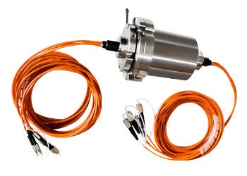
Fiber optic rotary joints (FORJs) are used to transmit high-speed data signals over optical fibers in systems that require continuous rotation. FORJs allows optical signals to be transmitted between stationary and rotating parts of a system, without any signal loss or degradation. The FORJ typically consists of a stationary component, a rotating component, and a fiber optic assembly that allows the transmission of light through the rotating joint.
RF rotary joints are used to transmit high-frequency electrical signals between stationary and rotating parts of a system. RF rotary joints allow the transmission of electromagnetic energy through a rotating joint, without signal loss or interference. RF rotary joints typically consist of two or more conductive rings that rotate with the system, allowing electrical signals to be transmitted through the joint.
How Does a Fiber Optic Rotary Joint Work?
A fiber optic rotary joint (FORJ) is a crucial component designed to facilitate the transmission of optical signals across rotating interfaces. This technology,specifically Integrated Fiber Optic Rotary Joints, is essential in applications that require continuous rotation without losing connectivity, such as in robotics, telecommunications, and medical equipment. Here’s a detailed overview of how a fiber optic rotary joint operates:
Basic Structure
Optical Fibers: The core of a fiber optic rotary joint consists of input and output optical fibers that carry light signals. These fibers are designed to transmit data with minimal loss and distortion.
Rotating Mechanism: The joint features a rotating component that allows the input and output fibers to remain connected while rotating. This mechanism is critical for maintaining a continuous optical path.
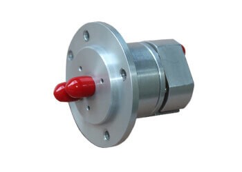
Protective Housing: A durable outer casing protects the internal components from environmental damage and provides structural integrity.
Signal Transmission
Light Propagation: Optical signals travel through the fibers using total internal reflection, which ensures that the light remains contained within the fiber. This method minimizes signal degradation.
Continuous Connection: As the joint rotates, the internal mechanisms keep the optical path uninterrupted. This allows signals to pass seamlessly from the input to the output fibers, even during rotation.
Rotational Functionality
Slip Ring Design: Similar to electrical slip rings, fiber optic rotary joint are designed to allow rotation without twisting the fibers. This prevents damage and ensures that the optical signals continue to flow without interruption.
Precision Alignment: High-quality manufacturing processes ensure that the fibers remain properly aligned during operation. Any misalignment can lead to signal loss, so maintaining alignment is critical.
Minimizing Signal Loss
Optical Path Efficiency: The design of the joint minimizes the distance that light must travel through the joint, reducing potential points of loss.
Mechanical Stability: Robust construction helps maintain alignment and stability during rotation, further reducing the likelihood of signal loss.
Applications of Fiber Optic Rotary Joints
Fiber optic rotary joints are widely used in various fields, including:
Surveillance & Video: Fiber optic rotary joints enable reliable data transmission in security cameras and monitoring systems, ensuring uninterrupted video feeds.
Wind Turbine: These joints facilitate communication between stationary and rotating components, enhancing the efficiency of wind energy systems.
Stage Lights: In theatrical productions, fiber optic rotary joints support the operation of stage lighting systems that require continuous rotation.
Entertainment Equipment: Fiber rotary joints are utilized in various entertainment devices, ensuring seamless signal transmission during performances.
Packing Machine: These joints assist in automated packing systems, allowing for efficient data transmission while the machines operate.
Robotic Arm: In robotics, fiber optic rotary joints provide continuous data flow, essential for the precise control of robotic movements.
Construction Machinery: Optical rotary joints are crucial in heavy machinery to maintain connectivity in rotating parts.
Medical: In medical imaging equipment, fiber optic rotary joints allow stable signal transmission while devices rotate or adjust.
Marine: Fiber optic rotary joints are used in marine applications to ensure reliable communication in dynamic environments.
Cable Reel: These joints help in cable reels by enabling data transfer while cables are in motion.
Automation: Fiber optic rotary joints are integral to automated systems, supporting communication between stationary and moving parts.
Measuring Equipment: In precision measurement tools, fiber optic rotary joints ensure accurate data transmission during operation.
Military: Fiber optic rotary joints are essential in military applications, providing reliable communication in demanding environments.
Radar & Antenna: These joints facilitate the transmission of data in radar systems, enhancing performance and reliability.
Optical Slip Ring Overview
An optical slip ring is a critical device used in applications that require the transmission of optical signals through a rotating interface. The fiber optic slip ring enables efficient data transmission in rotating systems, while the optical slipring is designed for seamless integration with fiber optic technology.This technology is vital for enabling seamless communication between stationary and rotating components, making it essential in various fields, including telecommunications, robotics, aerospace, and medical devices. By utilizing advanced optical technology, these slip rings allow for high-speed data transfer without the limitations typically associated with electrical connections and slip ring data transfer.
Key Features
Continuous Signal Transmission:
Optical slip rings facilitate the continuous transfer of optical signals without interruption, allowing for high-speed data transmission. This feature is particularly important in applications where movement or rotation occurs, such as robotic arms or rotating cameras. For instance, in robotic applications, a slip ring fiber optic can enable constant data flow, enhancing the robot’s ability to operate efficiently without losing signal integrity during its movements.
Compact Design:
Many optical slip rings are designed to be compact, making them suitable for installations with limited space and slip ring design.Their small footprint allows for easy integration into various systems without compromising performance. This compactness is particularly advantageous in environments like data centers or advanced manufacturing facilities, where space optimization is crucial.
High Bandwidth:
Optical slip rings support high data rates, making them ideal for applications requiring large amounts of data transfer, such as video surveillance and high-definition imaging. The ability to handle large bandwidth ensures that high-resolution video streams can be transmitted without lag or data loss, which is essential for modern surveillance systems.
Immunity to Electromagnetic Interference (EMI):
One of the significant advantages of using optical slip rings is their immunity to electromagnetic interference. This feature ensures reliable data transmission even in environments with strong electromagnetic fields, making them suitable for use in industries like aerospace and telecommunications, where such conditions are common.
Durability and Reliability:
Optical slip rings are typically designed to withstand harsh conditions, including temperature variations and mechanical stress. This durability ensures long-term performance in demanding environments, such as industrial applications where equipment may be exposed to extreme conditions. The robust design of fibre optic slip rings helps maintain consistent performance over time, reducing the need for frequent maintenance or replacements.
What is Pivoting Fiber Panel
A pivoting fiber panel is an innovative solution designed for efficient fiber management in telecommunications and data networking environments. This type of panel allows for easy access to fiber optic connections while optimizing space utilization, making it ideal for high-density applications such as data centers and server rooms. The pivoting design provides users with the flexibility to manage and maintain connections without compromising accessibility. In conjunction with fibre optic rotary joints, which facilitate the seamless transmission of optical signals, pivoting fiber panels create a highly efficient and organized network infrastructure.
Key Features
Space Efficiency:
The pivoting mechanism of the fiber panel allows it to swing out, providing direct access to the rear connections. This design maximizes space utilization, particularly in environments where every inch counts. It makes it easier to manage cables and connections, especially in tight spaces commonly found in server rooms and telecommunications cabinets. The integration of a fiber optic joint ensures that connections remain secure and easily accessible, enhancing overall efficiency.
Ease of Access:
One of the most significant advantages of a pivoting fiber panel is the ease of access it offers to technicians and network administrators. By simply swinging the panel open, users can quickly reach fiber connections, patch cords, and splicing trays without having to navigate around other equipment or cables. This accessibility reduces downtime during maintenance and troubleshooting, ultimately leading to more efficient operations.
Enhanced Cable Management:
Pivoting fiber panels often include features that facilitate better cable management. These features may consist of organized routing paths for fiber optic cables, securing mechanisms to prevent tangling or damage, and labeling options to help identify connections quickly. Additionally, when paired with fibre optic rotary joints, the panel can manage both static and rotating connections, ensuring that all data transmission needs are met without complication.
Modular Design:
Many pivoting fiber panels are modular, allowing for customization based on specific needs. Users can choose the number of ports, types of connectors, and additional features such as fiber splicing trays or integrated management tools. This flexibility ensures that the fiber management system can evolve as technology and user requirements change, enhancing the longevity of the installation.
Advantages
High-Quality Materials: Constructed for durability, ensuring reliable access for installers and network administrators.
Efficient Installation: Swing-out tray minimizes power cable movement, while the swing-open front panel allows easy access to patch cords.
Tool-Free Adapter Mounting: Saves time during installation by enabling quick adapter mounting without screws.
Versatile Mounting Options: Adjustable mounting ears accommodate various cabinet sizes.
Fiber Optic Rotary Joints & RF Rotary Joints
Both FORJ and RF rotary joints are devices that transmit signals through a rotary interface, which is useful in a variety of applications such as surveillance systems, military equipment, and industrial automation. Their specific application will depend on the system requirements for signal speed, frequency and accuracy.
FORJ and RF Rotary Unions Features
- Low Insertion Loss: FORJ and RF rotary joints are designed to minimize signal loss during transmission, ensuring high-quality signals and reliable performance.
- Compact size: FORJ and RF rotary unions are typically small and lightweight for use in applications where space is limited.
- Low maintenance: FORJ and RF rotary unions are designed for long-term, maintenance-free operation, with sealed housings that protect internal components from dust, moisture, and other environmental elements.
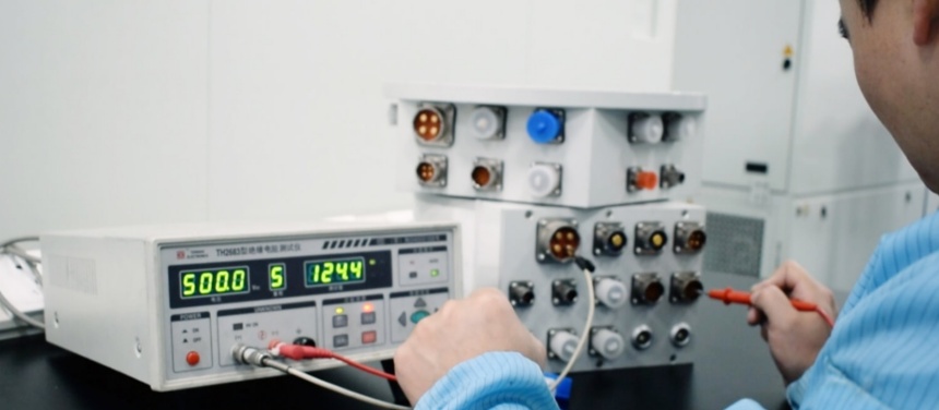
- High reliability: FORJ and RF rotary joints are designed to operate under extreme conditions, such as high temperature, high humidity and high vibration, and are highly resistant to wear and tear.
- Multi-channel: FORJ and RF rotary joints can be configured to support multi-channel, allowing multiple signals to be transmitted simultaneously.
FORJ and RF Rotary Unions are highly specialized devices designed to provide reliable and continuous signal transmission to rotary joints in a variety of industrial, military and scientific applications.
FAQs about Fiber Optic(FORJ) RF Rotary Joint
Do You Offer Multi-channel Fiber Optic Rotary Joint?
Yes. We offer both multi-channel and single FORJs.
What is Good for High Speed Serial Digital Signal Rotating Transmission?
High frequency/coaxial/waveguide rotary joints are good for high speed serial digital signal and analog signal rotating transmission.
Do Your FORJs Can Combined with Electrical Slip Rings?
Yes. We have solid plans for this situation, please ask us for the demo.
What the Singlemode Type Insertion Loss Will Be?
The insertion loss will be 0.5-1.0 dB under 1,310-1,550 nm wavelengths.
What is the Maximum Data Transfer Rate Supported by FORJs?
The maximum data transfer rate supported by FORJs depends on the specific device, but it can range from a few kilobits per second up to several gigabits per second.
Can FORJs Transfer Power As Well As Data?
Yes, some FORJs can transfer both power and data across a rotating interface, allowing for the transmission of electrical power to rotating components, such as motors or sensors.
What Are the Main Factors That Affect FORJ Performance?
The main factors that affect FORJ performance include insertion loss, return loss, bandwidth, polarization sensitivity, and temperature range.
Can RF Rotary Joints Be Customized for Specific Applications?
Yes, RF rotary joints can be customized for specific applications, such as high-speed data transfer, high-frequency ranges, and multiple channels.
What Factors Should Be Considered when Selecting an RF Rotary Joint?
Factors to consider when selecting an RF rotary joint include frequency range, VSWR, insertion loss, temperature range, size, and the number of channels.
What Are the Main Types of RF Rotary Joints?
The main types of RF rotary joints include coaxial, waveguide, and fiber optic.
What is the Difference Between a Single-channel and Multi-channel RF Rotary Joint?
A single-channel RF rotary joint can only transfer one RF signal at a time, while a multi-channel RF rotary joint can transfer multiple RF signals simultaneously.
Can RF Rotary Joints Be Integrated with Other Rotary Components?
Yes, RF rotary joints can be integrated with other rotary components, such as slip rings, shafts, and bearings, to provide a complete rotary solution.
What is a fiber optic rotary joint?
A fiber optic rotary joint (FORJ) is an essential device that enables the transmission of optical signals between stationary and rotating components in various applications. These joints are critical in scenarios where continuous rotation is necessary, such as in robotic systems, satellites, and high-tech cameras. The design of a FORJ allows for seamless communication without interrupting the flow of optical data, making it invaluable in modern telecommunications and industrial applications. Fiber optic rotary joints utilize advanced optical technologies to minimize signal loss and ensure high-quality data transmission, which is vital in maintaining the integrity of the transmitted signals. The ability to manage light signals effectively while accommodating rotational movement sets FORJs apart from traditional electrical rotary joints, which can suffer from signal degradation. As technology evolves, the demand for efficient and reliable communication systems increases, making fiber optic rotary joints crucial for ensuring consistent data flow in rotating environments.
What is the difference between RF and optical fiber?
The primary difference between RF (radio frequency) technology and optical fiber lies in the medium through which they transmit data. RF technology utilizes electromagnetic waves to carry information, while optical fiber transmits data using light signals that travel through glass or plastic fibers. One significant advantage of optical fiber is its capacity for higher bandwidth, allowing it to transmit more data over longer distances without signal loss. In contrast, RF signals can experience interference from various sources, leading to potential degradation in data quality. Additionally, optical fibers are immune to electromagnetic interference (EMI), which can disrupt RF communication. This makes optical fiber an ideal choice for applications requiring high-speed data transfer, such as telecommunications and internet services. Moreover, optical fibers are lighter and more compact than RF cables, making them easier to install in space-constrained environments. Ultimately, the choice between RF and optical fiber depends on specific application requirements, including distance, data rate, and susceptibility to interference.
What is an RF rotary joint?
An RF rotary joint is a specialized device designed to facilitate the transmission of radio frequency signals between stationary and rotating components. This technology is crucial in applications that involve continuous rotation, such as radar systems, satellite antennas, and telecommunications equipment. RF rotary joints allow for the seamless transfer of RF signals while enabling the components to rotate, which is essential for maintaining the functionality of rotating machinery. These joints are engineered to minimize signal loss and reflection, ensuring reliable performance in demanding environments. Typically, RF rotary joints employ a combination of conductive paths and dielectric materials to efficiently manage RF signals. The design of these joints can vary based on the specific application and frequency range required. By providing a reliable interface for RF transmission, RF rotary joints enhance the operational efficiency of various systems, contributing significantly to the reliability and effectiveness of modern communication and aerospace technologies.
Can you joint fiber optic cable?
Yes, fiber optic cables can be joined using a process known as fiber splicing, which allows for the creation of a continuous optical signal pathway between two cables. Splicing is essential for maintaining the integrity of the data being transmitted and is commonly used in telecommunications and network infrastructure. There are two main techniques for splicing fiber optic cables: fusion splicing and mechanical splicing. Fusion splicing involves aligning the two fiber ends precisely and then using an electric arc to melt them together, resulting in a strong, low-loss connection. This method is preferred for permanent installations due to its durability and minimal signal loss. On the other hand, mechanical splicing aligns the fibers and holds them together using an adhesive or special fixture, allowing for easier and quicker execution, albeit with slightly higher signal loss. Regardless of the method, successful fiber splicing requires specialized equipment and expertise to ensure optimal performance, allowing for effective data transmission in fiber optic networks.
Why is optical fiber better than coaxial cable?
Optical fiber is often considered superior to coaxial cable for several reasons, particularly in high-performance communication applications. One of the most significant advantages of optical fiber is its ability to transmit data at much higher speeds and over longer distances without signal degradation. Optical fibers utilize light signals, which can travel longer distances without the attenuation that is commonly experienced with coaxial cables. Additionally, optical fibers are immune to electromagnetic interference (EMI), allowing for clearer and more reliable data transmission in environments where electronic noise could disrupt signals carried by coaxial cables. Furthermore, optical fibers are lighter and thinner than coaxial cables, making them easier to install and manage, particularly in space-constrained environments. In terms of bandwidth, optical fibers can support much larger amounts of data simultaneously, which is crucial for modern high-speed internet and telecommunications applications. Overall, the advantages of speed, distance, immunity to interference, and capacity make optical fiber the preferred choice for many applications in today’s data-driven world.
Contact Our Team
Rotary Joints: Classification, Installation and Maintenance
The two categories of Rotary Joints are fiber optic rotary joints and RF rotary joints, so what is the use of rotary joints? How to install and maintain the rotary joint?
Try clicking the following article to learn about fiber optic swivel joints, how does a fiber optic swivel joint work? What is a radio frequency rotary joint and how does a coaxial rotary joint work?