A rotor resistance starter for a slip ring motor is an electrical device that is used to start and control the speed of a three-phase induction motor. It is composed of a rotor resistance, a collecting ring, and a set of contactors. The rotor resistance starter works by introducing an external resistance in the rotor circuit of the motor, which reduces the starting current and torque of the motor.
How Does It Work with the Collecting Ring?
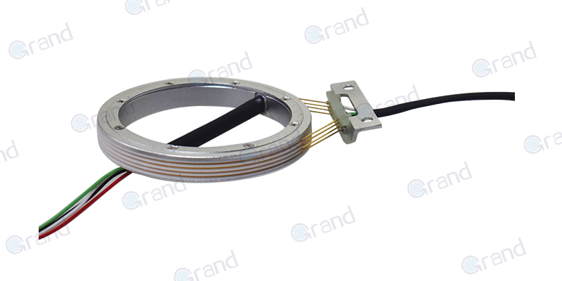
The collecting ring is used to connect the rotor resistance starter to the motor. The collecting ring is a metal ring that is connected to the rotor resistance starter. It is connected to the motor’s rotor winding, which allows the rotor resistance starter to control the motor’s speed. When the contactors are closed, the rotor resistance starter is connected to the motor, and the motor’s speed is controlled by the resistance of the rotor resistance starter.
What Are the Benefits of Using a Rotor Resistance Starter for Slip Ring Motor?
Using a rotor resistance starter for a slip ring motor has several benefits. First, it reduces the starting current and torque of the motor, which helps to protect the motor from damage due to a high starting current. Second, it allows the motor to be started at lower speeds, which helps to reduce wear and tear on the motor. Finally, it helps to reduce the amount of noise generated by the motor during operation.
The rotor resistance starter for the slip ring motor is a useful device that can help to reduce the starting current and torque of a three-phase induction motor. It works with the collecting ring to control the motor’s speed, and it has several benefits, including reducing the starting current and torque of the motor, allowing the motor to be started at lower speeds, and reducing the amount of noise generated by the motor during operation.
See What We Can Do