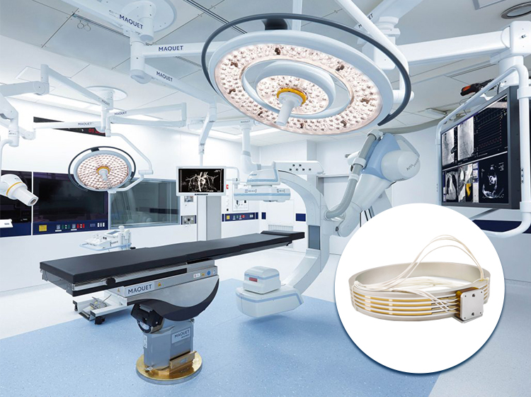
A slip ring is a very essential component of electromechanical devices and is used in an array of industries like radars in surveillance systems, microscopes, support arm lamps, wind turbines, automation equipment, rotating table, etc.
Its function is to provide electricity to the part from a stationary that rotates continuously in an assembly of equipment, resolves the continuous rotation of 360 degrees, and should have the feature to be able to rotate continuously in loops.
Differences between the slip ring and a commutator
· The function of a slip ring and a commutator is very similar except the slip ring is continuous whereas the commutator is segmented. · Slip rings, on the one hand, provide a continuous transfer of power, or data especially, in AC motors, as they transfer resistance to the rotor windings. · On the other hand, commutators belong to DC motors with the function of reversing the armature windings’ polarity of the current. · Flanged slip rings come with screws that are used to mount a slip ring and washers. The washers have this unique function to protect the rim against intemperate forces. If the machine uses the lock washers, flat washers should be positioned between the lock washer and the rim. · Slip rings that are used without the rims can be mounted with the use of the stator. The most common practice of doing this is to insert the body of the slip ring into a hole that is comparatively bigger than the OD, through the use of set screws, adhesives, or O-rings after which it is safely secured. · The rotor can be driven with a pliable drive combination to accommodate differences in the assembly of the machine and the axis of rotation slip rings. This process is done with the help of combinations of flexible coupling, Rubber tubing, and heat shrink tubing. For machines that run at 5 rotations per minute or less, the rotor lead combinations can be used as the flexible coupling.
· The external or radial loads cannot be taken care of by the slip ring’s bearings and are not designed to support in any way. The rotating parts should be designed, structured, and supported in a way to weaken the effect of axial and radial forces on the slip ring bearings to a bare minimum. · Dust and moisture are an enemy to the slip ring and hence should be taken care of to protect it from external environmental elements. If the installation of a slip ring happens in an outdoor setting then it must be made sure to be placed in a weatherproof setting to strengthen its longevity. · The slip ring should be designed in such a way that after the leads are secured, they should not touch or be in contact with any surface of the equipment as it rotates as it might lead to the death of the functions of the slip ring. While routing the wires, the leads shouldn’t be allowed to touch any side while loading on the slip ring. · The slip ring should be designed in such a way that after the leads are secured, they should not touch or be in contact with any surface of the equipment as it rotates as it might lead to the death of the functions of the slip ring. While routing the wires, the leads shouldn’t be allowed to touch any side while loading on the slip ring.
The process of mounting a slip ring
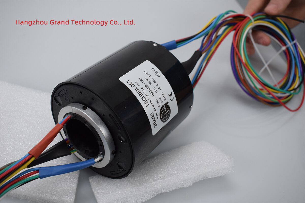
Figure 1
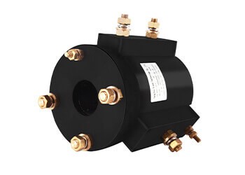
Figure 2
Install Slip Ring Methods
Installing a slip ring requires careful consideration of the application requirements and adherence to best practices to ensure reliable operation. Here are some common methods for installing slip rings:
Direct Mounting
Method: Attach the slip ring directly to the shaft or rotating part of the equipment.
Applications: Suitable for equipment with a dedicated mounting space for the slip ring.
Steps:
Ensure the shaft is clean and free of debris.
Align the slip ring’s bore with the shaft.
Slide the slip ring onto the shaft.
Secure the slip ring using set screws or other provided fasteners.
Connect the stationary part to a fixed bracket to prevent rotation.
Flange Mounting
Method: Use a mounting flange to secure the slip ring to a stationary part of the equipment.
Applications: Common in larger slip rings or those with specific mounting flanges.
Steps:
Position the slip ring flange against the mounting surface.
Align the bolt holes in the flange with those on the mounting surface.
Insert bolts through the aligned holes and tighten securely.
Ensure the slip ring’s rotor is properly aligned with the rotating shaft.
Through Bore Mounting
Method: Mount the slip ring around a central shaft, allowing other components to pass through the bore.
Applications: Used in applications requiring central cable or fluid passage.
Steps:
Position the slip ring over the shaft.
Align the slip ring bore with the shaft.
Slide the slip ring into place, ensuring it sits securely around the shaft.
Use clamps or set screws to secure the slip ring.
Connect the stationary part to a fixed bracket.
Bracket Mounting
Method: Secure the slip ring to a custom or pre-designed bracket.
Applications: Ideal for non-standard installations or where direct mounting is not possible.
Steps:
Design or select a bracket suitable for the slip ring and application.
Attach the slip ring to the bracket using screws or bolts.
Mount the bracket to the equipment’s stationary part.
Ensure proper alignment of the rotating part with the slip ring’s rotor.
Housing Mounting
Method: Install the slip ring inside a protective housing or enclosure.
Applications: Used in harsh environments to protect the slip ring from dust, moisture, and other contaminants.
Steps:
Place the slip ring inside the housing.
Secure the slip ring to the housing using internal mounts or brackets.
Mount the housing to the equipment.
Ensure seals and gaskets are properly installed to protect against environmental factors.
Clamping
Method: Use clamps to secure the slip ring to the shaft or equipment.
Applications: Temporary installations or where flexibility in positioning is required.
Steps:
Position the slip ring on the shaft or mounting surface.
Use suitable clamps to secure the slip ring.
Ensure the clamps are tight enough to prevent movement but not so tight as to damage the slip ring.
General Installation Tips
Alignment: Ensure the slip ring is properly aligned with the rotating shaft to avoid undue stress and wear.
Wiring: Route wires carefully to avoid tangling or interference with moving parts.
Lubrication: If required, apply appropriate lubrication to the slip ring to reduce friction and wear.
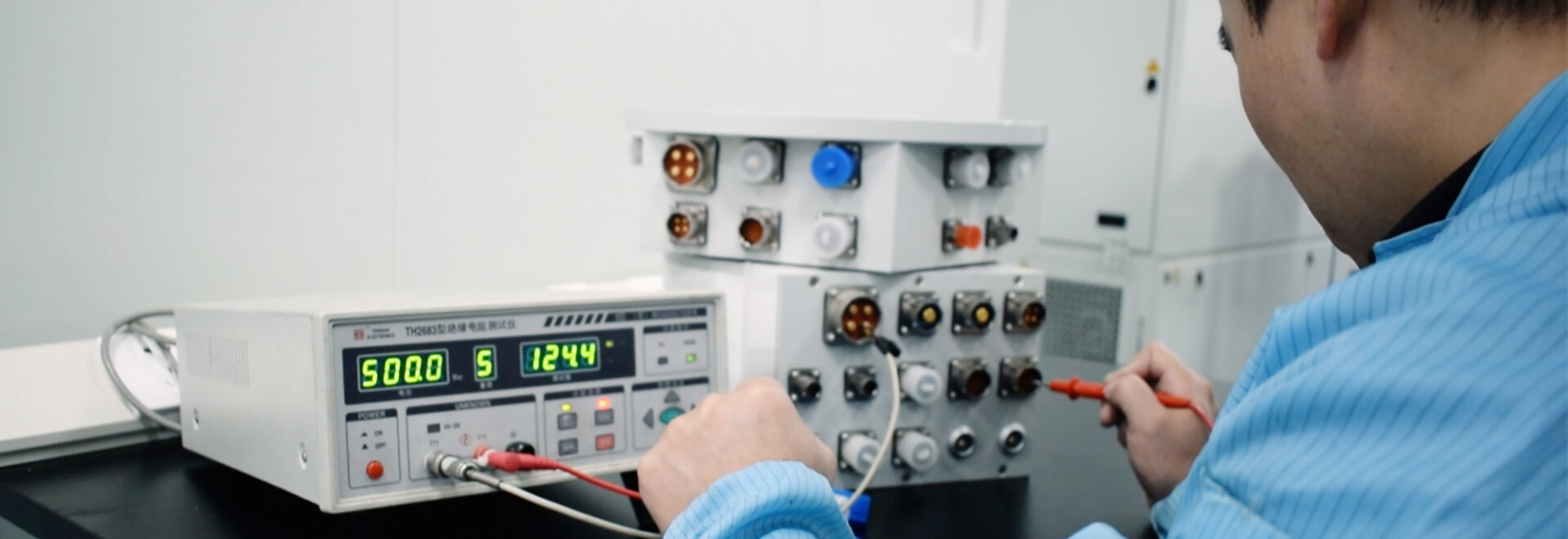
Testing: After installation, test the slip ring to ensure it operates correctly without noise or excessive resistance.
Maintenance: Regularly inspect and maintain the slip ring to ensure long-term reliability and performance.
Following these methods and tips will help ensure a successful installation and reliable operation of the slip ring in various applications
Factors to Consider When Choosing a Mounting Method
Choosing the right mounting method for a slip ring involves considering several factors to ensure optimal performance and longevity. Here are the key factors to consider:
1. Application Requirements
Rotational Speed: Ensure the mounting method can accommodate the required rotational speed without causing undue stress or wear on the slip ring.
Load Type: Consider whether the load is light or heavy, as this will influence the stability and robustness of the mounting method.
2. Space Constraints
Available Space: Assess the available space for mounting the slip ring. Some methods, like through bore or pancake slip rings, are more compact and suitable for tight spaces.
Accessibility: Ensure there is enough room for installation, maintenance, and wiring.
3. Environmental Conditions
Exposure to Elements: If the slip ring will be exposed to dust, moisture, or extreme temperatures, choose a mounting method that allows for protective housing or enclosures.
Vibration and Shock: Consider the level of vibration and shock the slip ring will be exposed to and choose a mounting method that provides adequate stability and support.
4. Mechanical Alignment
Alignment Precision: Ensure the mounting method allows for precise alignment between the slip ring’s rotor and stator to prevent mechanical stress and ensure smooth operation.
Flexibility: Some applications may require adjustable mounting methods to accommodate slight misalignments or changes in positioning.
5. Ease of Installation
Complexity: Consider the complexity of the mounting method. Simpler methods like direct or bracket mounting are easier and quicker to install.
Tools and Equipment: Assess the tools and equipment required for installation. Some methods may require specialized tools or expertise.
6. Maintenance Requirements
Accessibility for Maintenance: Choose a mounting method that allows easy access for regular inspection, cleaning, and maintenance.
Replacement and Repair: Consider how easily the slip ring can be removed and replaced if necessary.
7. Electrical and Signal Considerations
Wiring and Connections: Ensure the mounting method allows for secure and organized routing of wires and connections.
Signal Integrity: Consider methods that minimize interference and maintain the integrity of electrical and signal transmission.
8. Load-Bearing Capacity
Weight Support: Ensure the mounting method can support the weight of the slip ring and any attached components.
Dynamic Loads: Consider dynamic loads that may occur during operation and choose a method that provides adequate support.
9. Cost and Budget
Cost of Mounting Method: Assess the cost of the mounting method and ensure it fits within the project budget.
Long-Term Costs: Consider the long-term costs associated with maintenance and potential replacements.
10. Compatibility with Equipment
Integration with Existing Equipment: Ensure the mounting method is compatible with the existing equipment and does not interfere with other components.
Customization: Some applications may require customized mounting solutions to fit unique equipment setups.
By carefully considering these factors, you can choose the most suitable mounting method for your slip ring application, ensuring reliable performance and ease of maintenance.
Common Install Issues
Installing slip rings can present various challenges that may affect their performance and longevity. Here are some common installation issues and how to address them:
1. Misalignment
Issue: Misalignment between the slip ring’s rotor and stator can cause uneven wear, increased friction, and potential failure.
Solution: Ensure precise alignment during installation. Use alignment tools or fixtures to verify correct positioning. Regularly check and adjust alignment if necessary.
2. Improper Mounting
Issue: Incorrect mounting can lead to instability, vibration, and mechanical stress on the slip ring.
Solution: Follow the manufacturer’s guidelines for mounting. Use appropriate fasteners and ensure all connections are secure. Verify that the mounting surface is flat and stable.
3. Poor Electrical Connections
Issue: Loose or poorly connected wires can cause intermittent signals, electrical noise, or failure.
Solution: Ensure all electrical connections are secure and properly insulated. Use connectors and terminals recommended by the manufacturer. Avoid over-tightening, which can damage connections.
4. Environmental Exposure
Issue: Exposure to dust, moisture, extreme temperatures, or corrosive substances can degrade slip ring performance.
Solution: Use protective housings or enclosures to shield the slip ring from harsh environments. Choose slip rings designed for the specific environmental conditions of your application.
5. Excessive Vibration and Shock
Issue: High levels of vibration and shock can lead to mechanical damage and reduce the lifespan of the slip ring.
Solution: Install vibration dampeners or isolators. Ensure the mounting method provides adequate stability. Regularly inspect for signs of wear or damage.
Issue: Lack of proper lubrication can increase friction and wear on the slip ring’s contacts.
Solution: Follow the manufacturer’s recommendations for lubrication. Use appropriate lubricants and apply them at regular intervals. Avoid over-lubricating, which can attract dust and debris.
7. Cable Management Issues
Issue: Poorly managed cables can tangle, interfere with rotation, or cause signal degradation.
Solution: Use cable guides, clips, and strain reliefs to organize and secure cables. Ensure cables have enough slack to accommodate movement without causing tension.
8. Overloading
Issue: Exceeding the slip ring’s rated electrical or mechanical load can cause overheating, electrical failure, or mechanical damage.
Solution: Verify the slip ring’s load ratings and ensure they match the application requirements. Monitor the load during operation and adjust if necessary.
9. Incorrect Assembly
Issue: Assembling the slip ring incorrectly can lead to operational issues and premature failure.
Solution: Carefully follow the manufacturer’s assembly instructions. Verify that all components are correctly positioned and secured before operation.
10. Lack of Regular Maintenance
Issue: Neglecting regular maintenance can result in accumulated wear and tear, leading to unexpected failures.
Solution: Implement a regular maintenance schedule. Inspect the slip ring for signs of wear, clean contacts, check connections, and apply lubrication as needed.
11. Compatibility Issues
Issue: Using a slip ring that is not compatible with the specific application or equipment can lead to performance problems.
Solution: Ensure the slip ring is suitable for the application’s electrical, mechanical, and environmental requirements. Consult with the manufacturer if unsure about compatibility.
12. Improper Handling
Issue: Mishandling during installation can cause physical damage to the slip ring.
Solution: Handle the slip ring with care, avoiding excessive force or impact. Use appropriate tools and techniques during installation.
Addressing these common issues proactively can help ensure a successful installation and reliable operation of slip rings in various applications.
Styles of Slip Ring Mounting
1) Installation through bore style
This installation is done by fixing the rotary for the inner ring and outer ring. These are also called electrical slip rings and consist of a hole in the center.
2) Installation through Pneumatic hybrid style
This kind of slip ring can be rotated 360 degrees and is used specifically for industrial usage
3) Installation with rotor flange slip ring
This is the one that is present with a flange on the rotor and is secured with the help of screws. It also uses the mount of anti- rotor pole to balance the equipment
4) Stator flange slip ring installation instruction
In this, the flange is located on the exterior of the ring and has the feature of rotating without being fixed to the cable provided it’s a miniature.
5) Bore rotor flange slip ring installation
This consists of a hole in the middle with the rotor part rotating and the stator part as fixed but it comes with the unique characteristic of working as well with the rotor part as fixed and the stator part rotating.
6) PCB slip ring installation instruction
This uses the PCB board as a substrate which fixes the ring to the board by pressing them together and coating them with shrapnel and contacts. One characteristic feature is here the PCB slip ring is installed separately individually between the rotor and the stator. This ensures that the rings have sufficient pressure and concentricity.
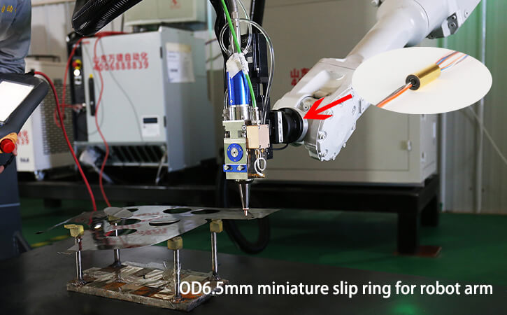
7) Installation for Multi-channel FORJ
The fiber optic rotary joint is also called fiber optic slip ring which has the capability to treat fiber optics as transmission data which facilitates resolving data transmission between system components of the rotary joint. This is suitable to use in places where large-volume data transmission is required from a fixed position to a rotating position. It is helpful in improving the mechanical property and helps reduce damage to the fiber optic caused by joint rotating.
See What We Can Do
About Author
Hangzhou Grand Technology
Hello everyone, I am the founder of Hangzhou Grand Technology. I run a factory in China that manufactures and develops slip rings and rotary joints since 2011. The purpose of this article is to share knowledge about slip rings and rotary joints from the perspective of Chinese suppliers.